Background
The Tastic RFID Thief was first introduced by Bishop Fox in 2013 at both Defcon and Blackhat. This tool is a long-range RFID reader that is modified to be portable, read RFID/NFC tags and store tag UID’s (Unique Identifier). These captured UID’s can later be written to blank RFID tags in order to obtain phyiscal access to otherwise restricted sites.
The design that I used and one that I would recommend is the Long Range RFID reader + ESPKey combination. If you have never heard of the ESPKey, it is an implantable logic analyzer and debugger for use with the wiegand protocol. It has no battery and is powered from the reader that it is attached to. The ESPKey when powered acts as a wireless access point allowing the user to connect to the access point and store/see tag UID’s as they are scanned in real time. If you have never heard of the wiegand protocol, I would recommend taking a read of these resources as a bit of a primer:
The tastic RFID thief also made a couple of appearances in Mr. Robot:
 |
 |
Build
In addition to the normal tools (multimeter, flux, solder, soldering iron), the following hardware, or variations of are required:
- Long Range RFID reader.
- ESPKey.
- 4x 3.7v Li-Ion 18650 rechargeable batteries.
- 2x 18650 Dual battery holders.
- A switch (rocker, toggle or pushbutton).
- Buck Module. (Reduces voltage)
- Boost Module. (Boosts voltage)
For the Aussie’s reading this, you can quickly grab everything you need besides the ESPKey and long range reader unit from JayCar:
DC-DC Boost Module - (Input 3V-35V / Output 4V-35V)
DC-DC Buck Module - (Input 4.5V / Output 3V-34V)
18650 Rechargeable Li-Ion Battery 2600mAh 3.7V
Illuminated Rocker Switch - (Rated to 240v)
To begin with a reader is required. There are a few common long range units that are fit for purpose and have been used successfuly. The 3 units below represent 3 out of 4 of HID’s product families:
| RFID Product Family | Frequency | Long Range Reader | Datasheet |
|---|---|---|---|
| HID Prox | 125Khz (LF) | HID MaxiProx 5375 | HID MaxiProx 5375 |
| Indala Prox | 125Khz (LF) | Indala Long-Range Reader 620 | Indala Prox 620 |
| iClass | 13.56Mhz (HF) | iClass - R90 Long Range Reader | iClass R90 |
Personally, for my build I decided to go with the HID MaxiProx 5375, as it reads all of the LF HID formats and these tags are still very common. Long range RFID readers are quite expensive but you can find good deals on used units on Ebay or Amazon.
For the ESPKey there are a few retailers to choose from:
Alternatively as the ESPKey project is open source it is possible to just build your own. The Gerber files and schematic are located Here.
Assuming you have collected all of the required hardware, this schematic from netspi can be used for the build. The schematic is self explanatory, just connect wires via soldering or inserting into the screw down terminals according to the diagram (from A «» A, B «» B etc):
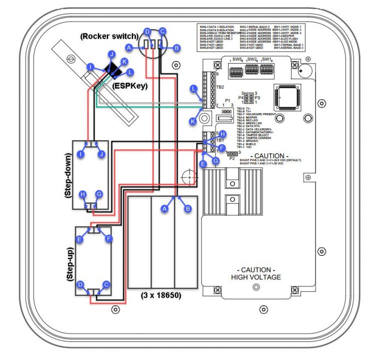
Schematic

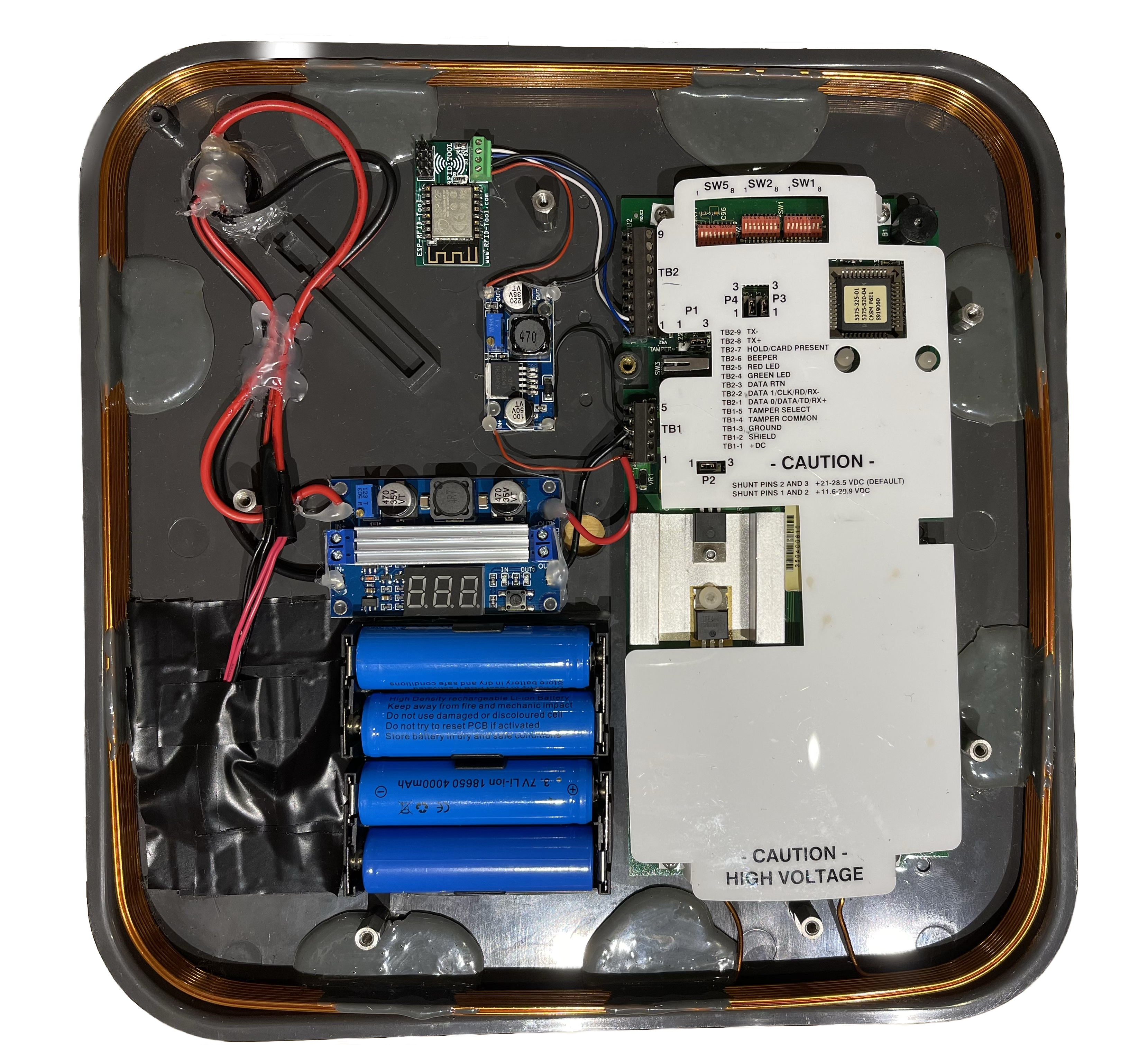
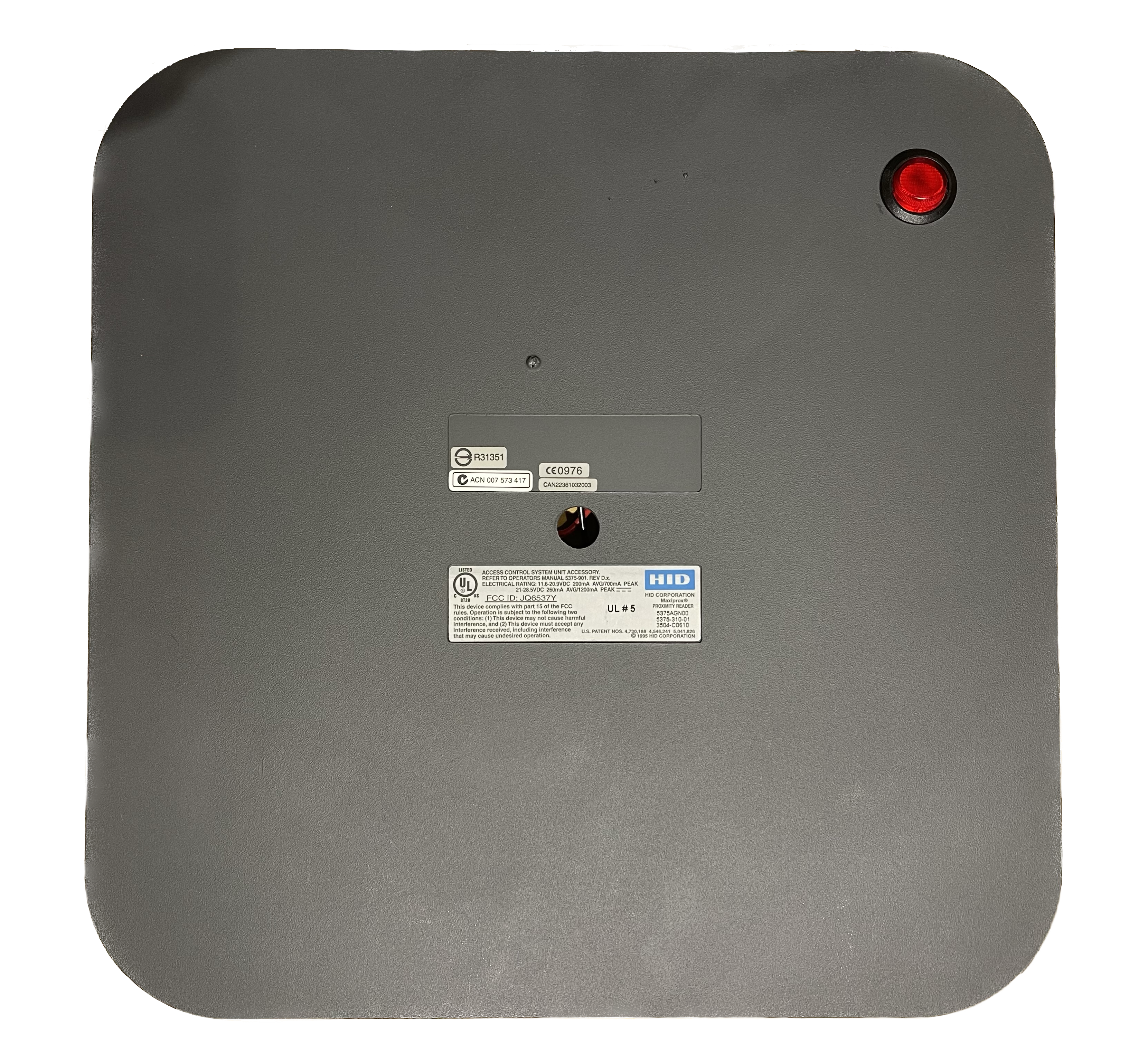
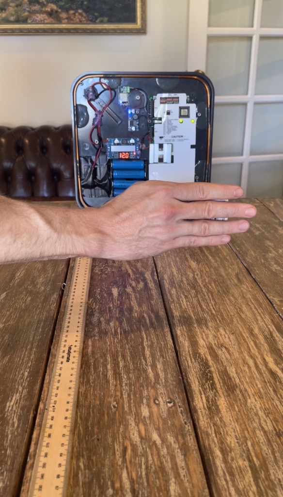
The only modification required to the reader unit shell is to use a dremel to make a 20mm hole (if you are using the linked rocker switch) on the back of the unit where you would like the rocker switch to be placed. The finished front and rear of the unit should end up looking something similar to this:
Front - Internal
Rear - External
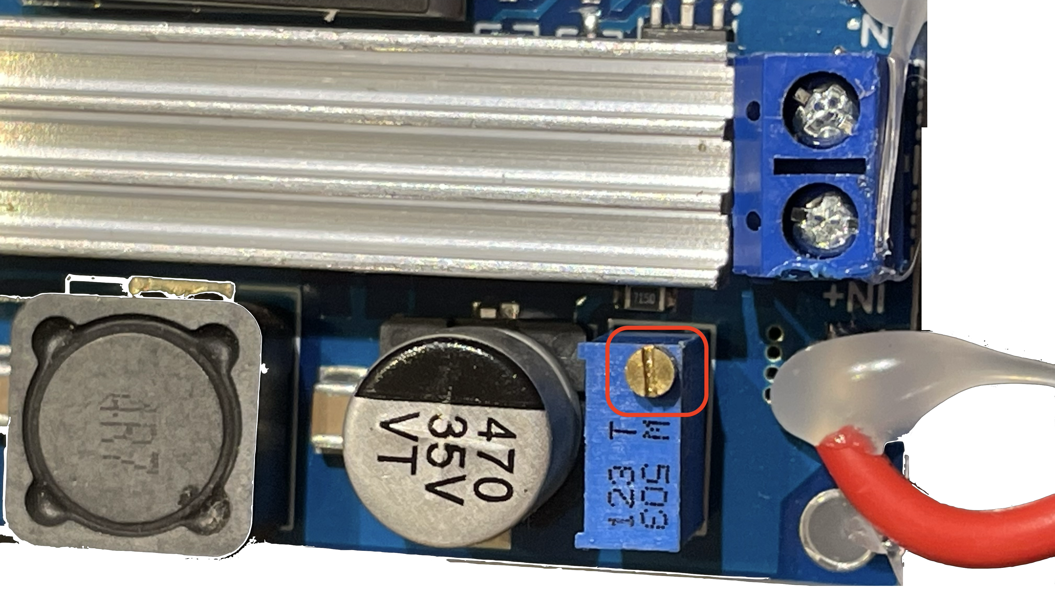
With the wiring now complete, the voltage for the buck and boost modules needs to be set. To do this take a small flat head screwdriver and rotate the screw on the potentiometer until the correct voltage is set.
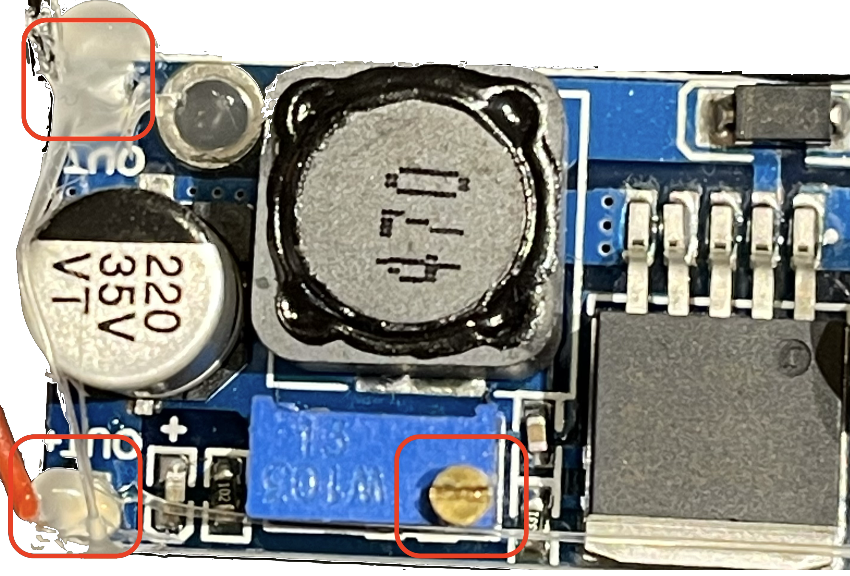
This is a simple process when using the linked boost module as the output voltage is displayed on the LED screen. For the buck module, measure the output voltage with a multimeter by placing the multimeter probes on -ve OUT and +ve OUT solder pads or wire ends as marked below while tuning the potentiometer until the required voltage is set.
The target voltage for the buck module is between 4.5v - 17v (I set 5v). The target voltage for the boost module is either 12v or 24v (I set 12v). When using more than 1 battery holder you will have to decide whether to wire the batteries in either series or parallel (I wired in series). Either will work but if wiring in parallel make sure that the wires are of a sufficient gauge to handle the increase in amperage.
If you do choose to set 12v you will need to move the shunt labelled P2 onto pins 1 and 2, for 24v shunt pins 2 and 3. When tuning the potentiometers remove the +ve and -ve wires from the screw down terminals on the ESPkey and reader unit.
Boost and Buck Module Potentiometers
 |
 |
With the wiring and voltage set, now is the time to test the unit. The unit should emit a series of beeps which indicates that the autotune process is running. The autotune feature on the MaxiProx 5375 reader attempts to compensate for interference. When the autotune has completed the front left LED indicator light should remain green and the front right, red. When a card is scanned the unit should emit a loud beep and the indicator light should briefly flash green before turning back to red.
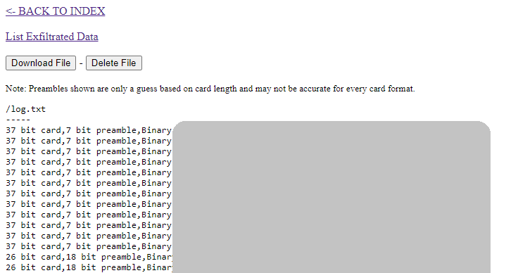
Any scanned UID’s will be automatically saved to the ESPKey in non-volative memory, so after collecting UID’s there is no requirement to keep the device powered on. To download the data for writing to a blank (T5577) LF tag with the proxmark3, connect to the ESPKey’s access point and navigate to http://192.168.1.1. From here you can access the log file and watch live as UID’s are scanned or download captured credentials. It’s also a good idea to take the time to configure the access point by changing the default SSID and password for the ESPKey.
At this stage, if you are following this guide while building a unit, you have probably noticed that the Piezo buzzer makes a very loud beep every time a tag is scanned. Beeping loudly in public is not ideal, so to quickly disable the buzzer here are a few options:
- Desolder the Buzzer.
- Cut the trace on the board.
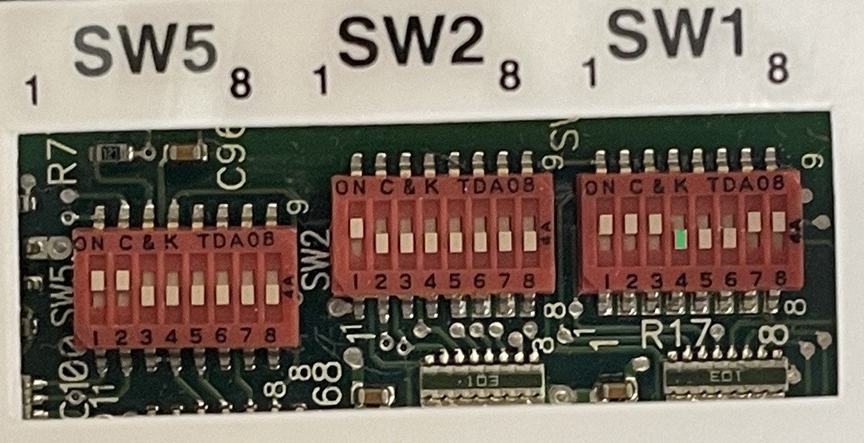
- Flip the dip switch.
I would recommend flipping the dip switch instead of desoldering unless space requirements dictate removal. The dipswitch to set to the OFF position is SW1 (Switch 1) jumper 4 located here:
Range Test
The final step is to test read range.
I set up the reader with a 100cm ruler and then slowly moved a T5577 tag until I could see the right LED light up green, indicating a successful read. With my unit I achieved an average read range of 42cm which is more than enough distance required to walk past a tag without being awkwardly close.
Safety
Finally, if you have no experience with electronics here are a few safety tips:
- If you use leaded solder, ensure you have enough ventilation while soldering or use a suitable respirator.
- Wash your hands thoroughly if you are touching solder and don’t eat while you work (lead is toxic).
- Don’t touch the capacitors at all (even when the unit is off), or internal circuitry while the unit is powered.